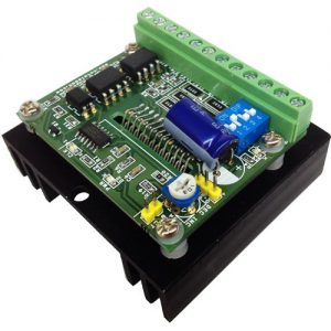
Driving Bipolar Stepper Motors By Pic 16f84 Projects
In previous blogs we learned the basics of stepper motors and how they function. Also discussed was the many uses at which stepper motors can be used. The next step in these articles is to take a bit more in depth look at the two different types of two-phase stepper motors. There are two basic winding arrangements for the electromagnetic coils in a two phase stepper motor, one being bipolar and the other unipolar.
- Bipolar Stepper Motor Driver Circuit
- Bipolar Stepper Motor Controller Circuit
- Bipolar Stepper Motor Controller
- Bipolar Stepper Motor Driver
- Bipolar Stepper Driver Circuit
Bipolar Stepper Motor Driver Circuit
Unipolar Stepper Motors
The unipolar stepper motor operates with one winding with a center tap per phase. Each section of the winding is switched on for each direction of the magnetic field. Each winding is made relatively simple with the commutation circuit, this is done since the arrangement has a magnetic pole which can be reversed without switching the direction of the current.

Bipolar Stepper Motor Controller Circuit
In most cases, given a phase, the common center tap for each winding is the following; three leads per phase and six leads for a regular two phase stepper motor. You will usually see that both these phases are often joined internally, this makes the stepper motor only have five leads. Often a stepper motor controller will be used to activate the drive transistors in the proper order. Since it is quite easy to operate these stepper motors, they are often very popular among hobbyists and are usually the cheapest way to get precise angular movements.
Bipolar Stepper Motors
With bipolar stepper motors there is only a single winding per phase. The driving circuit needs to be more complicated to reverse the magnetic pole, this is done to reverse the current in the winding. This is done with a H-bridge arrangement, however there are several driver chips that can be purchased to make this a more simple task.
Bipolar Stepper Motor Controller
Unlike the unipolar stepper motor, the bipolar stepper motor has two leads per phase, neither of which are common. Static friction effects do happen with a H-bridge with certain drive topologies, however this can be reduced with dithering the stepper motor signal at a higher frequency.
Figure 2: ICs for Unipolar and Bipolar Driving. UNIPOLAR a) b) BIPOLAR Dedicated integrated circuits have dramatically simplified stepper motor driving. To apply these ICs desi-gners need little specific knowledge of motor driving techniques, but an under-standing of the basics will help in finding the best solution. Stepper Motors and It's Working Principles: In this tutorial I will show, how to interface stepper motor with microcontroller and in this case I will use pic18f2550 microcontroller.Basically stepper motor works step by step.It can rotate 360 degree by the movements of equal steps.They are available stepper motor with steps 200, 180, 144, 72, 24 with rotation angles 1.8°, 2°, 2.5°, 5. And the following table shows driving sequence for the other rotation direction: Interfacing PIC16F877A with bipolar stepper motor circuit: The following image shows circuit schematic diagram of this project where two pushbuttons are used to choose motor rotation direction and a potentiometer to control motor speed.
This is a brief introduction on how a stepper motor may vary between unipolar and bipolar.
Bipolar Stepper Motor Driver
Bipolar stepper motors can be a bit more difficult to operate, and the unipolar motor does feature twice the amount of wire in the same space. Different projects will require different types and settings of stepper motors. Browse the large selection to find the perfect one for your needs.
Bipolar Stepper Driver Circuit
Can you give me some recommendations for driving these motors? I was thinking of using a PIC and tc4423 or 4469 with FETs. I really want to Microstep these motors. As I said this is a small setup but I want to have good accuracy. I don't want to discuss the mechanics just the electronics and maybe the driving software/controller interface.
I have looked at various chips and just want some advice.
I hope someone can help.
Thanks
